What Are Two Reasons to Create a Network Baseline? (Choose Two.)
Contents
Introduction
This certificate describes baselining concepts and procedures for highly available networks. It includes critical success factors for network baselining and thresholding to help evaluate success. It too provides significant detail for baseline and threshold processes and implementation that follow best exercise guidelines identified by Cisco's High Availability Services (HAS) team.
This document takes you step-by-step through the procedure of baselining. Some current network management arrangement (NMS) products can help automate this procedure, however, the baselining procedure remains the aforementioned whether yous use automated or manual tools. If you use these NMS products, yous must adapt the default threshold settings for your unique network surroundings. It is of import to have a process to intelligently choose those thresholds so that they are meaningful and correct.
Baseline
What is a Baseline?
A baseline is a process for studying the network at regular intervals to ensure that the network is working as designed. It is more a single written report detailing the health of the network at a certain signal in fourth dimension. By post-obit the baseline procedure, you can obtain the following information:
-
Gain valuable information on the wellness of the hardware and software
-
Determine the current utilization of network resources
-
Brand accurate decisions near network warning thresholds
-
Identify current network bug
-
Predict futurity problems
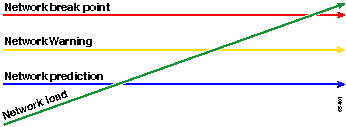
Another way of looking at the baseline is illustrated in the following diagram.
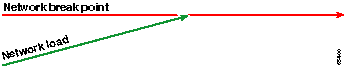
The red line, the network break point, is the indicate at which the network will break, which is determined through the knowledge of how the hardware and software perform. The greenish line, the network load, is the natural progression of load on the network as new applications are added, and other such factors.
The purpose of a baseline is to make up one's mind:
-
Where your network is on the light-green line
-
How fast the network load is increasing
-
Hopefully predict at what point in time the two will intersect
By performing a baseline on a regular basis, you can find out the current land and extrapolate when failures will occur and fix for them in advance. This also helps yous to make more informed decisions almost when, where, and how to spend upkeep coin on network upgrades.
Why a Baseline?
A baseline process helps you lot to identify and properly programme for disquisitional resource limitation bug in the network. These issues can be described as control plane resources or data aeroplane resource. Command plane resources are unique to the specific platform and modules within the device and tin exist impacted by a number of issues including:
-
Information utilization
-
Features enabled
-
Network design
Command aeroplane resources include parameters such every bit:
-
CPU utilization
-
Memory utilization
-
Buffer utilization
Data aeroplane resources are impacted only by the blazon and quantity of traffic and include link utilization and backplane utilization. By baselining resource utilization for disquisitional areas, you can avoid serious performance issues, or worse, a network meltdown.
With the introduction of latency-sensitive applications such equally voice and video, baselining is now more important than e'er. Traditional Manual Control Protocol/Internet Protocol (TCP/IP) applications are forgiving and permit for a certain amount of delay. Vox and video are User Datagram Protocol (UDP) based and do not allow for retransmissions or network congestion.
Due to the new mix of applications, baselining helps you to understand both command plane and data airplane resources utilization issues and to proactively plan for changes and upgrades to ensure continued success.
Data networks have been effectually for many years. Until recently, keeping the networks running has been a fairly forgiving process, with some margin for error. With the increasing credence of latency-sensitive applications such as Voice over IP (VoIP), the job of running the network is becoming harder and requires more precision. In gild to be more precise and to give a network administrator a solid foundation upon which to manage the network, it is important to have some idea of how the network is running. To do this, you must go through a process called a baseline.
Baseline Objective
The objective of a baseline is to:
-
Make up one's mind the current condition of network devices
-
Compare that condition to standard performance guidelines
-
Set up thresholds to alert yous when the status exceeds those guidelines
Due to the large amount of data and the amount of fourth dimension it takes to clarify the information, you must first limit the scope of a baseline to make it easier to acquire the procedure. The nigh logical, and at times the near beneficial, place to start is with the core of the network. This role of the network is usually the smallest and requires the almost stability.
For the sake of simplicity, this document explains how to baseline one very important Simple Network Management Protocol Management Information Base (SNMP MIB): cpmCPUTotal5min. cpmCPUTotal5min is the five-infinitesimal decaying average of a Cisco router'due south key processing unit of measurement (CPU), and is a control airplane performance indicator. The baseline will exist performed on a Cisco 7000 serial router.
Once yous have learned the process, you tin use it to whatever information available in the vast SNMP database which is bachelor in most Cisco devices, such equally:
-
Integrated Services Digital Network (ISDN) usage
-
Asynchronous Transfer Mode (ATM) prison cell loss
-
Free organization retentiveness
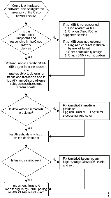
Core Baseline Flowchart
The following catamenia chart shows the basic steps of the cadre baseline process. While products and tools are available to perform some of these steps for you, they tend to have gaps in flexibility or ease of use. Even if you plan to use network management arrangement (NMS) tools to perform baselining, this is all the same a adept exercise in studying the process and understanding how your network really works. This procedure may also take some of the mystery out of how some NMS tools work since well-nigh tools essentially practice the same things.
Baseline Procedure
Step 1: Compile a Hardware, Software, and Configuration Inventory
Information technology is extremely important that you lot compile an inventory of hardware, software, and configuration for several reasons. First, Cisco SNMP MIBs are, in some cases, specific to the Cisco IOS release that you are running. Some MIB objects are replaced with new ones or are, at times, completely eliminated. The hardware inventory is most important after the data is collected since the thresholds you need to set up after the initial baseline are oftentimes based on the type of CPU, amount of memory, and so on, on the Cisco devices. The configuration inventory is besides important to make sure that you know the current configurations: You may desire to change device configurations later on your baseline to melody buffers, and so on.
The most efficient way to do this part of the baseline for a Cisco network is with CiscoWorks2000 Resources Director Essentials (Essentials). If this software is installed correctly in the network, Essentials should have the current inventories of all devices in its database. You simply demand to look at the inventories to see if there are any issues.
The following table is an example of a Cisco Router Form software inventory study exported from Essentials, and then edited in Microsoft Excel. From this inventory, notice that you take to use SNMP MIB information and Object Identifiers (OIDs) found in the 12.0x and 12.1x Cisco IOS releases.
| Device Name | Router Type | Version | Software Version |
|---|---|---|---|
| field-2500a.embu-mlab.cisco.com | Cisco 2511 | M | 12.i(1) |
| qdm-7200.embu-mlab.cisco.com | Cisco 7204 | B | 12.one(1)E |
| voip-3640.embu-mlab.cisco.com | Cisco 3640 | 0x00 | 12.0(3c) |
| wan-1700a.embu-mlab.cisco.com | Cisco 1720 | 0x101 | 12.1(4) |
| wan-2500a.embu-mlab.cisco.com | Cisco 2514 | L | 12.0(i) |
| wan-3600a.embu-mlab.cisco.com | Cisco 3640 | 0x00 | 12.1(3) |
| wan-7200a.embu-mlab.cisco.com | Cisco 7204 | B | 12.1(1)East |
| 172.sixteen.71.fourscore | Cisco 7204 | B | 12.0(5T) |
If Essentials is not installed in the network, yous can utilise the UNIX command line tool snmpwalk from a UNIX workstation to notice the IOS version. This is shown in the following case. If you're not certain how this command works, type man snmpwalk at the UNIX prompt for more than information. The IOS version will exist important in when you begin choosing which MIB OIDs to baseline, since the MIB objects are IOS dependent. Also observe that by knowing the router type, you tin can afterwards brand determinations equally to what the thresholds should be for CPU, buffers, then on.
nsahpov6% snmpwalk -v1 -c private 172.xvi.71.80 system organization.sysDescr.0 : Brandish STRING- (ascii): Cisco Internetwork Operating System Software IOS (tm) 7200 Software (C7200-JS-Yard), Version 12.0(5)T, RELEASE SOFTWARE (fc1) Copyright (c) 1986-2001 past cisco Systems, Inc. Compiled Friday 23-Jul-2001 23:02 by kpma system.sysObjectID.0 : OBJECT IDENTIFIER: .iso.org.dod.internet.private.enterprises.cisco.ciscoProducts.cisco7204
Step 2: Verify that the SNMP MIB is Supported in the Router
Now that you lot have an inventory of the device yous want to poll for your baseline, you lot can begin to choose the specific OIDs yous want to poll. It saves a lot of frustration if you verify, ahead of fourth dimension, that the information you want is actually there. The cpmCPUTotal5min MIB object is in the CISCO-Process-MIB.
To observe the OID you desire to poll, you need a conversion table which is bachelor on Cisco's CCO web site. To access this web site from a spider web browser, get to the Cisco MIBs folio, and click the OIDs link.
To access this spider web site from an FTP server, type ftp://ftp.cisco.com/pub/mibs/oid/. From this site, you can download the specific MIB that has been decoded and sorted by OID numbers.
The post-obit example is extracted from the CISCO-Procedure-MIB.oid tabular array. This example shows that the OID for the cpmCPUTotal5min MIB is .1.iii.6.ane.4.i.9.9.109.1.1.1.1.5.
Note:Don't forget to add a "." to the beginning of the OID or you'll go an mistake when you try to poll it. You too need to add a ".1" to the stop of the OID to instantiate information technology. This tells the device the instance of the OID yous are looking for. In some cases, OIDs have more than than one instance of a particular type of data, such as when a router has multiple CPUs.
ftp://ftp.cisco.com/pub/mibs/oid/CISCO-Process-MIB.oid ### THIS FILE WAS GENERATED BY MIB2SCHEMA "org" "1.3" "dod" "1.iii.6" "internet" "i.iii.6.one" "directory" "i.iii.six.i.1" "mgmt" "ane.iii.6.i.2" "experimental" "ane.3.vi.1.3" "private" "1.3.half dozen.i.four" "enterprises" "1.iii.6.one.4.1" "cisco" "1.three.6.1.four.ane.9" "ciscoMgmt" "ane.3.half-dozen.1.4.one.9.nine" "ciscoProcessMIB" "i.3.vi.1.iv.1.9.9.109" "ciscoProcessMIBObjects" "i.three.6.1.4.1.ix.ix.109.1" "ciscoProcessMIBNotifications" "i.three.6.1.4.1.9.9.109.2" "ciscoProcessMIBConformance" "ane.3.six.1.4.i.9.9.109.3" "cpmCPU" "1.3.six.1.4.1.9.ix.109.1.ane" "cpmProcess" "1.3.6.one.iv.1.9.9.109.1.ii" "cpmCPUTotalTable" "1.three.6.1.4.1.nine.nine.109.1.i.1" "cpmCPUTotalEntry" "1.3.vi.ane.4.1.9.9.109.1.1.1.i" "cpmCPUTotalIndex" "1.three.6.1.four.1.nine.9.109.ane.1.one.ane.ane" "cpmCPUTotalPhysicalIndex" "1.3.six.one.4.1.9.nine.109.one.i.1.1.2" "cpmCPUTotal5sec" "1.3.6.1.4.1.9.nine.109.ane.ane.i.1.3" "cpmCPUTotal1min" "1.3.half-dozen.1.four.1.9.9.109.1.1.ane.1.iv" "cpmCPUTotal5min" "ane.3.half dozen.1.iv.1.9.ix.109.1.1.1.one.five"
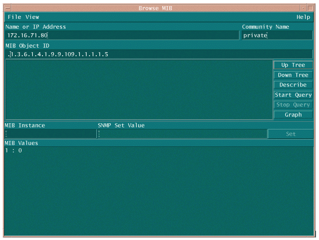
At that place are two common ways to poll the MIB OID to brand sure it's available and operation. It is a good idea to practise this before you start the bulk data collection and so that you don't waste matter time polling something that is non there and cease up with an empty database. One manner to do this is to use a MIB walker from your NMS platform such as HP OpenView Network Node Director (NNM), or CiscoWorks Windows, and enter the OID you want to check.
The following is an case from HP OpenView SNMP MIB walker.
Another easy way to poll the MIB OID is to use the UNIX command snmpwalk equally shown in the post-obit example.
nsahpov6% cd /opt/OV/bin nsahpov6% snmpwalk -v1 -c private 172.16.71.80 .ane.iii.six.1.4.1.ix.9.109.1.1.i.1.v.1 cisco.ciscoMgmt.ciscoProcessMIB.ciscoProcessMIBObjects.cpmCPU.cpmCPUTotalTable.cpmCPUTotalEntry.cpmCPUTotal5min.1 : Gauge32: 0
In both examples, the MIB returned a value of 0, meaning that for that polling cycle the CPU averaged 0 percent utilization. If you have difficulty getting the device to reply with the correct data, try pinging the device and accessing the device by way of Telnet. If yous still take a problem, bank check the SNMP configuration and the SNMP community strings. Yous may need to observe an alternative MIB or another version of IOS to make this piece of work.
Pace 3: Poll and Record Specific SNMP MIB Object from the Router
There are several ways to poll MIB objects and record the output. Off-the-shelf products, shareware products, scripts, and vendor tools are available. All front-stop tools apply the SNMP go process to obtain the information. The main differences are in the flexibility of the configuration and the way in which the information is recorded in a database. Once more, look at the processor MIB to encounter how these various methods work.
Now that you know the OID is supported in the router, you demand to decide how frequently to poll it and how to record it. Cisco recommends that the CPU MIB be polled at v-minute intervals. A lower interval would increase the load on the network or device, and since the MIB value is a v-minute average anyway it would not exist useful to poll it more than frequently than the averaged value. It is too mostly recommended that baseline polling have at least a two-week menstruation so that you tin can clarify at least two weekly business concern cycles on the network.
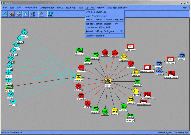
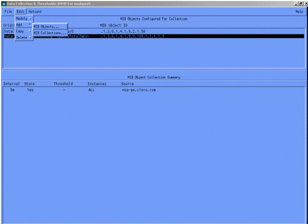
The following screens show you how to do add MIB objects with HP OpenView Network Node Manager version six.one. From the master screen, select Options > Data Drove & Thresholds.
And then select Edit > Add > MIB Objects.
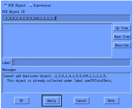
From the menu, add the OID string and click Utilize. You take now entered the MIB object into the HP OpenView platform so that information technology can exist polled.
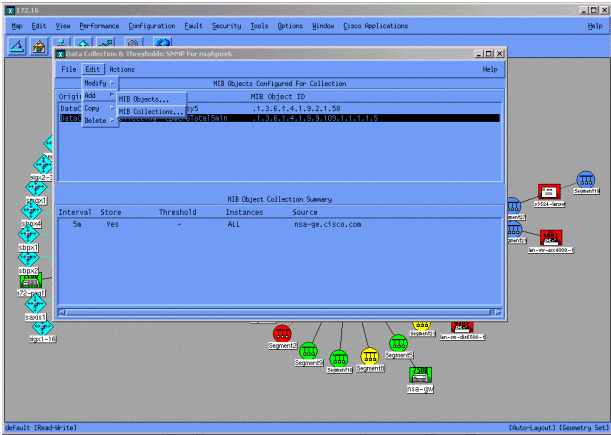
Y'all must next let HP OpenView know what router to poll for this OID.
From the Information Collection menu, select Edit > Add > MIB Collections.
In the Source field, enter the Domain Naming System (DNS) name or IP address of the router to be polled.
Select Store, No Thresholds from the Set Collection Manner list.
Set the Polling Interval to 5m, for v minute intervals.
Click Apply.
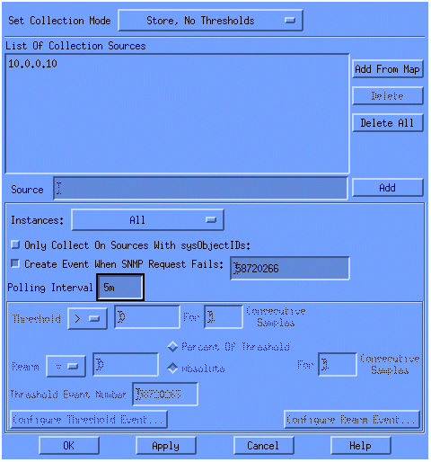
You must select File > Save for the changes to accept impact.
To verify that the collection is set up properly, highlight the collection summary line for the router and select Actions > Examination SNMP. This checks to see if the community cord is correct and will poll for all instances of the OID.
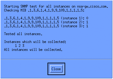
Click Close, and allow the collection run for a week. At the end of the weekly menstruum, extract the information for analysis.
The data is more than easily analyzed if yous dump information technology to an ASCII file and import it into a spreadsheet tool such as Microsoft Excel. To do this with HP OpenView NNM, you lot tin use the command line tool, snmpColDump. Each drove configured writes to a file in the /var/opt/OV/share/databases/snmpCollect/ directory.
Extract the data to an ASCII file chosen testfile with the post-obit control:
snmpColDump /var/opt/OV/share/databases/snmpCollect/cpmCPUTotal5min.1 > testfile
Notation:cpmCPUTotal5min.1 is the database file that HP OpenView NNM created when the OID polling began.
The test file generated appears similar to the following instance.
03/01/2001 xiv:09:10 nsa-gw.cisco.com 1 03/01/2001 fourteen:14:10 nsa-gw.cisco.com i 03/01/2001 fourteen:nineteen:10 nsa-gw.cisco.com 1 03/01/2001 14:24:10 nsa-gw.cisco.com i 03/01/2001 14:29:10 nsa-gw.cisco.com 1 03/01/2001 14:34:ten nsa-gw.cisco.com ane 03/01/2001 14:39:10 nsa-gw.cisco.com 1 03/01/2001 14:44:10 nsa-gw.cisco.com 1 03/01/2001 14:49:ten nsa-gw.cisco.com 1 03/01/2001 14:54:10 nsa-gw.cisco.com 1 03/01/2001 14:59:10 nsa-gw.cisco.com i 03/………
Once the test file output is on your UNIX station, you lot can transfer it to your PC using File Transfer Protocol (FTP).
Yous tin can too assemble the information using your own scripts. To do this, perform an snmpget for the CPU OID every v minutes and dump the results into a .csv file.
Step 4: Analyze Information to Determine Thresholds
Now that you accept some information, you tin begin to analyze it. This phase of the baseline determines the threshold settings you lot tin can use that are an authentic measure out of performance or error and will not set up off too many alarms when you lot turn on threshold monitoring. One of the easiest ways to exercise this is to import the data into a spreadsheet such as Microsoft Excel and plot a besprinkle chart. This method makes it very easy to run into how many times a particular device would have created an exception alert if you were monitoring information technology for a sure threshold. It is not advisable to turn on thresholds without doing a baseline, since this may create alert storms from devices that accept exceeded the threshold you lot accept called.
To import the test file into an Excel spreadsheet, open Excel and select File > Open up and select your data file.
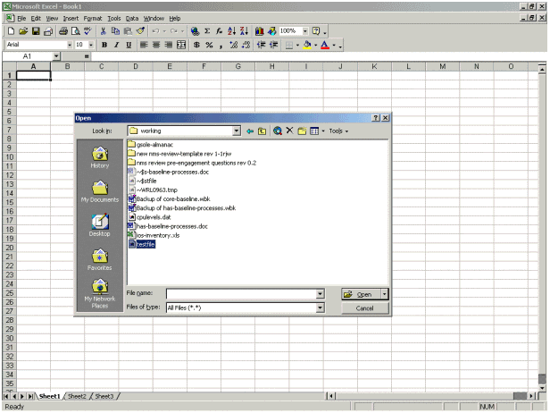
The Excel awarding so prompts yous through importing the file.
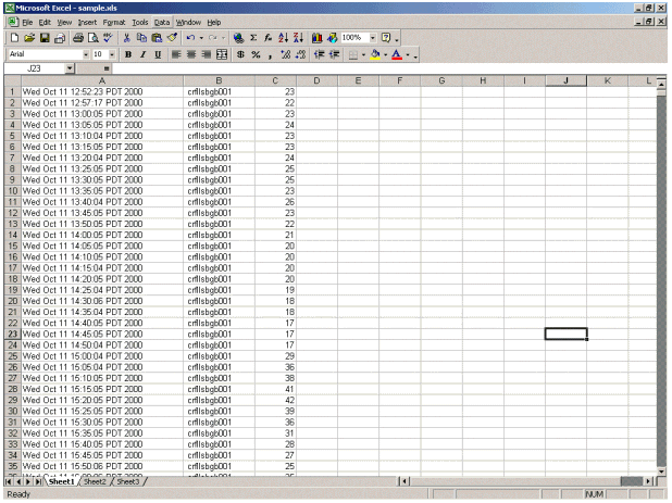
When finished, the imported file should look similar to the following screen.
A scatter nautical chart allows you to more than easily visualize how various threshold settings would work on the network.
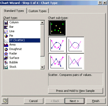
To create the scatter nautical chart, highlight column C in the imported file and then click the Chart Wizard icon. Then follow the steps through Chart Sorcerer for edifice a scatter nautical chart.
In Chart Sorcerer step 1, as shown below, select the Standard Types tab, and select the XY (Scatter) chart type. And then click Side by side.
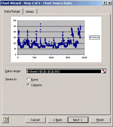
In Chart Wizard step ii, as shown below, select the Information Range tab and select the data range and the Columns option. Click Next.
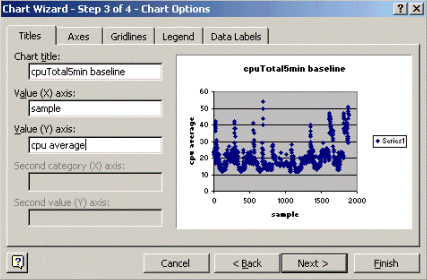
In Chart Sorcerer stride 3, as shown below, enter the nautical chart title and the X and Y axis values, and then click Next.
In Chart Wizard stride 4, select whether you want the scatter chart on a new folio or as an object in the existing page.
Click Finish to place the chart in your desired location.
"What If?" Analysis
You tin now apply the scatter chart for analysis. However, before proceeding, you demand to enquire the following questions:
-
What does the vendor (in this example the vendor is Cisco) recommend as a threshold for this MIB variable?
In general, Cisco recommends that a cadre router does not exceed threescore percent average CPU utilization. Sixty percent was chosen because a router needs some overhead in instance information technology experiences trouble or the network has some failures. Cisco estimates that a core router needs approximately 40 percent CPU overhead in instance a routing protocol has to recalculate or reconverge. These percentages vary based on the protocols you use and the topology and stability of your network.
-
What if I employ 60 pct equally the threshold setting?
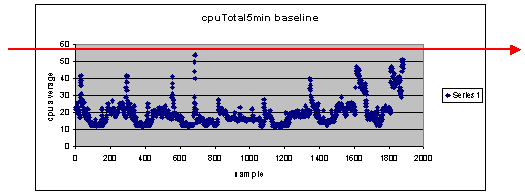
If yous depict a line across the scatter nautical chart horizontally at 60, y'all'll see that none of the data points exceed 60 percent CPU utilization. And so a threshold of 60 assail your network direction system (NMS) stations volition not accept set off a threshold warning during the polling catamenia. A pct of 60 is acceptable for this router. All the same, find in the besprinkle chart that some of the data points are close to 60. Information technology would be squeamish to know when a router is nearing the 60 percent threshold and then y'all tin can know ahead of time that the CPU is budgeted 60 percentage and have a plan for what to do when it reaches that point.
-
What if I set the threshold to fifty percent?
It is estimated that this router reached 50 percent utilization four times during this polling cycle and would accept generated a threshold alarm each fourth dimension. This process becomes more important when yous look at groups of routers to see what the different threshold settings would do. For example, "What if I set the threshold at 50 percent for the entire core network?" You lot see, information technology is very difficult to choose just one number.
CPU Threshold "What If" Analysis
One strategy you can apply to make this easier is the Gear up, Ready, Become threshold methodology. This methodology uses three threshold numbers in succession.
-
Ready—the threshold you set every bit a predictor of what devices will likely demand attending in the future
-
Fix—the threshold that is used as an early indicator, which alerts you to begin planning for a repair, reconfiguration, or upgrade
-
Go—the threshold that you and/or the vendor believe is a fault status and requires some activity to repair information technology; in this instance it is 60 percent
The following tabular array shows the strategy of the Ready, Set, Go strategy.
| Threshold | Action | Result |
|---|---|---|
| 45 percent | Investigate further | List of options for action plans |
| 50 percent | Formulate action plan | List of steps in action plan |
| threescore per centum | Implement action plan | Router no longer exceeds thresholds. Back to Set up mode |
The Ready, Fix, Go methodology changes the original baseline chart discussed earlier. The following diagram shows the changed baseline chart. If you can identify the other intersection points on the chart, you now take more than time to programme and react than y'all did earlier.
Detect that in this process, attention is focused on the exceptions in the network and is non concerned with other devices. Information technology is assumed that equally long as devices are beneath thresholds, they are fine.
If you take these steps thought out from the beginning, you will exist well prepared for keeping the network healthy. Performing this type of planning is besides extremely useful for budget planning. If y'all know what your elevation 5 become routers, your middle fix routers, and your lesser set routers are, you tin can easily plan on how much budget you will need for upgrades based on what kind of routers they are and what your action plan options are. The same strategy can exist used for broad-expanse network (WAN) links or whatever other MIB OID.
Pace 5: Fix Identified Immediate Problems
This is i of the easier parts of the baseline process. Once you lot have identified which devices exceed the get threshold, you should make an action plan to get those devices back under threshold.
You can open up a case with Cisco'due south Technical Assistance Center (TAC) or contact your Systems Engineer for available options. You should not assume that getting things dorsum nether threshold will toll y'all coin. Some CPU issues tin be resolved by irresolute the configuration to ensure that all processes are running in the most efficient manner. For example, some Access Control Lists (ACLs) can make a router CPU run very high due to the path the packets accept through the router. In some cases, yous tin can implement NetFlow switching to modify the packet switching path and reduce the touch on of the ACL on the CPU. Whatever the bug are, it is necessary to get all routers back under threshold in this step so y'all tin can implement the thresholds later without the risk of flooding the NMS stations with too many threshold alarms.
Step 6: Test Threshold Monitoring
This step involves testing the thresholds in the lab using the tools you will use in the production network. There are two common approaches to monitoring thresholds. You must decide which method is best for your network.
-
Poll and compare method using an SNMP platform or other SNMP monitoring tool
This method uses more network bandwidth for polling traffic and takes upwards processing cycles on your SNMP platform.
-
Use Remote Monitoring (RMON) Alarm and Event configurations in the routers so they send an alarm only when a threshold is exceeded
This method reduces network bandwidth usage simply also increases memory and CPU utilization on the routers.
Implementing a Threshold using SNMP
To ready up the SNMP method using HP OpenView NNM, select Options > Data Drove & Thresholds every bit you did when you set up the initial polling. This fourth dimension, however, select Shop, Check Thresholds rather than Store, No Thresholds in the collections bill of fare. After yous fix the threshold, y'all can raise the CPU utilization on the router by sending it multiple pings and/or multiple SNMP walks. You may have to lower the threshold value if you can't force the CPU high enough to trip the threshold. In any case, you lot should ensure that the threshold machinery is working.
One of the limitations of using this method is that you cannot implement multiple thresholds simultaneously. Yous would need iii SNMP platforms to set three different simultaneous thresholds. Tools such every bit Concur Network Health ![]() and Trinagy Tendency
and Trinagy Tendency ![]() allow multiple thresholds for the same OID instance.
allow multiple thresholds for the same OID instance.
If your organization tin only handle one threshold at a time, you may consider the Ready, Set, Go strategy in series fashion. That is, when the prepare threshold is reached continually, begin your investigation and raise the threshold to the set level for that device. When the set level is reached continually, begin to codify your activity plan and raise the threshold to the become level for that device. Then when the get threshold is reached continually, implement your action program. This should work merely besides as the three simultaneous threshold method. It simply takes a little more time changing the SNMP platform threshold settings.
Implementing a Threshold using RMON Alert and Event
Using RMON alarm and event configurations, you can take the router monitor itself for multiple thresholds. When the router detects an over-threshold condition, information technology sends an SNMP trap to the SNMP platform. You must have an SNMP trap receiver set up in your router configuration for the trap to exist forwarded. At that place is a correlation between an alarm and event. The alert checks the OID for the given threshold. If the threshold is reached, the alarm process fires the event procedure which tin can either transport an SNMP trap message, create an RMON log entry, or both. For more item on this command, come across RMON Alarm and Outcome Configuration Commands.
The following router configuration commands has the router monitor cpmCPUTotal5min every 300 seconds. It volition burn event 1 if the CPU exceeds sixty percent and volition fire event 2 when the CPU falls dorsum to twoscore percent. In both cases, an SNMP trap message will be sent to the NMS station with the community private cord.
To utilise the Gear up, Set, Go method, use all of the post-obit configuration statements.
rmon event 1 trap private description "cpu hit60%" owner jharp rmon effect two trap private description "cpu recovered" owner jharp rmon warning 10 cpmCPUTotalTable.ane.5.1 300 absolute rising sixty 1 falling 40 2 owner jharp rmon event 3 trap private clarification "cpu hit50%" possessor jharp rmon event four trap individual clarification "cpu recovered" owner jharp rmon alarm 20 cpmCPUTotalTable.1.v.1 300 absolute rise 50 3 falling 40 4 owner jharp rmon event 5 trap individual clarification "cpu striking 45%" owner jharp rmon event vi trap private description "cpu recovered" owner jharp rmon alarm 30 cpmCPUTotalTable.1.5.1 300 absolute ascent 45 5 falling twoscore 6 possessor jharp
The post-obit example shows the output of the bear witness rmon warning control that was configured past the above statements.
zack#sh rmon warning Alarm 10 is active, owned by jharp Monitors cpmCPUTotalTable.i.5.1 every 300 second(southward) Taking absolute samples, last value was 0 Rising threshold is lx, assigned to consequence 1 Falling threshold is 40, assigned to consequence 2 On startup enable rise or falling warning Warning 20 is active, owned by jharp Monitors cpmCPUTotalTable.1.5.i every 300 2nd(s) Taking absolute samples, final value was 0 Ascent threshold is 50, assigned to event three Falling threshold is 40, assigned to event 4 On startup enable rising or falling alarm Alarm 30 is agile, owned past jharp Monitors cpmCPUTotalTable.i.5.one every 300 2nd(southward) Taking absolute samples, last value was 0 Rising threshold is 45, assigned to event v Falling threshold is 40, assigned to event six On startup enable ascent or falling alarm
The following example shows the output of the evidence rmon event control.
zack#sh rmon event Event ane is active, owned by jharp Description is cpu hit60% Result firing causes trap to community private, last fired 00:00:00 Upshot 2 is active, endemic by jharp Description is cpu recovered Event firing causes trap to community private, final fired 02:twoscore:29 Result three is active, owned by jharp Clarification is cpu hit50% Event firing causes trap to community private, last fired 00:00:00 Result iv is active, endemic by jharp Description is cpu recovered Consequence firing causes trap to community private, last fired 00:00:00 Event 5 is agile, endemic by jharp Description is cpu hit 45% Event firing causes trap to community private, last fired 00:00:00 Event 6 is active, owned by jharp Description is cpu recovered Consequence firing causes trap to community private, last fired 02:45:47
You may want to try both of these methods to see which method best suits your environs. Y'all may even discover that a combination of methods works well. In any case, testing should be done in a lab surround to ensure that everything works correctly. After testing in the lab, a limited deployment on a small group of routers will allow yous to examination the process of sending alerts to your Operations Center.
In this example, you will have to lower the thresholds to test the procedure: Trying to artificially raise the CPU on a production router is non recommended. Y'all should also ensure that when the alerts come into the NMS stations at the Operations Middle, there is an escalation policy to make certain that y'all are informed when devices exceed thresholds. These configurations have been tested in a lab with Cisco IOS Version 12.one(7). If you encounter whatever bug, you should check with Cisco Applied science or Systems Engineers to encounter if you have a bug in your IOS version.
Pace 7: Implement Threshold Monitoring using SNMP or RMON
Once you have thoroughly tested threshold monitoring in the lab, and in a limited deployment, you are set to implement thresholds beyond the core network. You lot can now systematically go through this baseline procedure for other important MIB variables on your network, such every bit buffers, free retention, cyclic redundancy cheque (CRC) errors, AMT cell loss, and so on.
If you use RMON alarm and upshot configurations, y'all can now finish polling from your NMS station. This volition reduce the load on your NMS server and volition reduce the amount of polling data on the network. By systematically going through this procedure for important network health indicators, you could easily come up to the indicate that the network equipment are monitoring themselves using RMON Alarm and Event.
Additional MIBs
Afterward you have learned this process, you may want to investigate other MIBs to baseline and monitor. The following subsections present a cursory list of some OIDs and descriptions that you may detect useful.
Router MIBs
Memory characteristics are very helpful in determining the wellness of a router. A good for you router should almost always have bachelor buffer infinite with which to work. If the router begins to run out of buffer space, the CPU will accept to work harder to create new buffers and to try to find buffers for incoming and approachable packets. An in-depth discussion of buffers is beyond the scope of this certificate. Nonetheless, as a general rule, a healthy router should accept very few, if any, buffer misses and should not have any buffer failures, or a cypher complimentary memory status.
| Object | Clarification | OID |
|---|---|---|
| ciscoMemoryPoolFree | The number of bytes from the memory pool that are currently unused on the managed device | 1.three.half dozen.i.iv.ane.9.9.48.1.1.1.6 |
| ciscoMemoryPoolLargestFree | The largest number of contiguous bytes from the retentivity puddle that are currently unused | i.iii.vi.1.4.1.9.9.48.one.i.one.seven |
| bufferElMiss | The number of buffer element misses | 1.three.6.1.four.1.9.two.i.12 |
| bufferFail | The number of buffer allocation failures | 1.3.6.1.iv.one.9.2.one.46 |
| bufferNoMem | The number of buffer create failures due to no complimentary memory | ane.3.6.1.four.ane.9.ii.1.47 |
Catalyst Switch MIBs
| Object | Description | OID |
|---|---|---|
| cpmCPUTotal5min | Overall CPU busy percentage in the last five-minute menses. This object deprecates the avgBusy5 object from the OLD-CISCO-SYSTEM-MIB | 1.3.six.1.4.1.9.nine.109.1.1.1.5 |
| cpmCPUTotal5sec | Overall CPU busy percentage in the final five-second period. This object obsolesces the busyPer object from the OLD-CISCO-System-MIB | i.three.half-dozen.1.4.1.9.9.109.one.1.1.iii |
| sysTraffic | The percentage of bandwidth utilization for the previous polling interval | 1.3.6.1.iv.1.ix.5.1.1.8 |
| sysTrafficPeak | The tiptop traffic meter value since the last time the port counters were cleared or the system started | ane.3.6.1.4.1.nine.5.1.1.19 |
| sysTrafficPeaktime | The time (in hundredths of a 2nd) since the peak traffic meter value occurred | 1.3.half dozen.1.4.1.ix.5.1.1.20 |
| portTopNUtilization | Utilization of the port in the system | 1.3.6.1.4.1.9.5.i.20.2.one.4 |
| portTopNBufferOverFlow | The number of buffer overflows of the port in the system | 1.3.6.1.4.1.nine.5.1.twenty.two.1.ten |
Serial Link MIBs
| Object | Description | OID |
|---|---|---|
| locIfInputQueueDrops | The number of packets dropped because the input queue was full | 1.three.six.1.four.ane.9.2.2.i.i.26 |
| locIfOutputQueueDrops | The number of packets dropped considering the output queue was full | one.3.6.1.4.1.9.2.2.1.1.27 |
| locIfInCRC | The number of input packets that had cyclic redundancy checksum errors | 1.iii.6.1.4.1.9.two.ii.one.i.12 |
RMON Alarm and Event Configuration Commands
Alarms
RMON alarms can exist configured with the following syntax:
rmon warning number variable interval {delta | accented} rising-threshold value [event-number] falling-threshold value [event-number] [owner string]
| Chemical element | Description |
|---|---|
| number | The alarm number, which is identical to the alarmIndex in the alarmTable in the RMON MIB. |
| variable | The MIB object to monitor, which translates into the alarmVariable used in the alarmTable of the RMON MIB. |
| interval | The fourth dimension, in seconds, the alarm monitors the MIB variable, which is identical to the alarmInterval used in the alarmTable of the RMON MIB. |
| delta | Tests the modify betwixt MIB variables, which affects the alarmSampleType in the alarmTable of the RMON MIB. |
| absolute | Tests each MIB variable directly, which affects the alarmSampleType in the alarmTable of the RMON MIB. |
| ascension-threshold value | The value at which the alarm is triggered. |
| event-number | (Optional) The upshot number to trigger when the rising or falling threshold exceeds its limit. This value is identical to the alarmRisingEventIndex or the alarmFallingEventIndex in the alarmTable of the RMON MIB. |
| falling-threshold value | The value at which the alarm is reset. |
| owner string | (Optional) Specifies an possessor for the alarm, which is identical to the alarmOwner in the alarmTable of the RMON MIB. |
Events
RMON events can be configured with the post-obit syntax:
rmon upshot number [log] [trap community] [clarification string] [owner string]
| Chemical element | Description |
|---|---|
| number | Assigned event number, which is identical to the eventIndex in the eventTable in the RMON MIB. |
| log | (Optional) Generates an RMON log entry when the event is triggered and sets the eventType in the RMON MIB to log or log-and-trap. |
| trap community | (Optional) SNMP community string used for this trap. Configures the setting of the eventType in the RMON MIB for this row as either snmp-trap or log-and-trap. This value is identical to the eventCommunityValue in the eventTable in the RMON MIB. |
| clarification string | (Optional) Specifies a clarification of the outcome, which is identical to the event description in the eventTable of the RMON MIB. |
| owner string | (Optional) Owner of this event, which is identical to the eventOwner in the eventTable of the RMON MIB. |
RMON Alarm and Event Implementation
For detailed information about RMON alarm and issue implementation, delight read the RMON Alarm and Event Implementation section of the Network Management Systems All-time Practices white paper.
Related Data
- Technical Support and Documentation - Cisco Systems
Source: https://www.cisco.com/c/en/us/support/docs/availability/high-availability/15112-HAS-baseline.html
0 Response to "What Are Two Reasons to Create a Network Baseline? (Choose Two.)"
Post a Comment